
Requirements
The eurorack power supply monitor provides high speed current measurements and supply control on all three eurorack supply rails for the purpose of characterizing power consumption and debugging power supply issues.
Hardware Requirements
| Requirement | Rationale |
|---|---|
| The module shall accept eurorack power via either 10-pin or 16-pin euroack power connector | Allow for keyed connectors and compatibility with any supply input |
| The module shall provide eurorack power to a single DUT module via both 10-pin and 16-pin eurorack power connector | Again, compatible with any module/power cable |
| The module shall by powered only by +/- 12 V supplies. | Since you can't be sure of having a 5V rail |
| The module shall communicate with a host computer via a USB connector on the front panel. | Usage, convenience. |
| The module shall provide a means of enabling all three eurorack supplies via software. | For monitoring power consumption during startup. |
| For all three rails, the module shall measure current in the range of 0 to 400 mA | Gives some headroom above the 250 mA that is the highest current consumption i've seen on popular modules |
| For all three rails, the module shall measure current with 5 mA resolution or better. | Seems like a lot of modules are specified in 5 mA resolution, and this should be achievable without too much difficulty. |
| The module shall measure current with at least 20 kHz bandwidth. | This is the audio range, which probably the most interesting frequency range for audio modules. I would like 80 kHz, but ADC sample rate may be a limiting factor, and I want to avoid an external ADC if possible. |
| For all three rails, the module shall measure voltage with 50 mV resolution or better | This should be easily achievable at 9-bits and 12 V. This is really just for sanity checking and detecting upstream supply issues like the supply overcurrenting and dropping out. |
| For all three rails, the module shall measure voltage with at least 100 Hz bandwidth. | It really doesn't need to be fast, and I don't want to take away from the current measurement if I can help it. |
| The module shall produce no more than 100 mV of voltage drop at 400 mA on any mointored rail. | Fairly arbitrary - just don't mess with the DUT's supplies too much. This could conceivably be a problem when you add the power switch so this might need revisiting? Might re-specify at 250 mA since the 400 mA figure is overhead. |
| The module shall provide a means of switching a reference load on each supply rail for calibration. | This is intentionally a little vague, but at the very least there should be a switch (FET) and connector for connecting an external load that can be turned on and off. Ideally there would be some kind of current reference on board that could be switched in for calibration, but this may be expensive or out of scope. |
| The module shall provide enable and fault status LEDs for all three supply rails | Quick visual feedback |
| The module shall provide a physical power switch to enable and disable all three rails. | Panic button and convenience. |
| The module shall provide overcurrent proctection and switch off if any rail draws more than 500 mA. | Peace of mind when you're smoke-testing a module. The hardware can respond faster than you can, and this is probably easier than including a 7-segment display or sthg. |
| The module shall provide a front-panel MCU prog pushbutton. | For reprogramming the Teensy more easily. |
| The module depth shall not exceed 60 mm at the lower edge and 95 mm at the upper edge. | This gives about 5mm margin on my current setup. The board can be trapezoidal if it comes to it |
| The module PCB height shall not exceed 110 mm. | Basic eurorack dimensions + a tiny bit of margin to make the fit easy and the numbers nice. |
Software Requirements
| Requirement | Rationale |
|---|---|
|
The module shall provide a means of triggering on: * current waveforms * voltage waveforms * manual power switch * software power switch |
For capturing transient events |
| The module shall provide a means of triggering a fixed-length capture. | For capturing transient events |
| It shall be possible to view realtime waveform and spectrum traces on a host computer. | Basic usage |
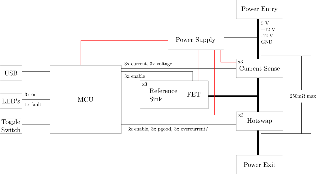
Block Diagram
Component Packages
Normally my preference is to avoid leadless parts, but as I'm imagining the layout of this thing I could see some advantage in having smaller parts for switching, since it seems like I'm gonna want to route power in more or less a straight shot and will need to stick the switched between supply traces.
Part Selections
Currently the biggest unknowns are the power switching and current reference circuitry. The power switching circuitry also needs to provide overcurrent protection, meaning it needs some amount of current sense capability. This implies that the current sense and power switching circuit may use a single controller depending on what's available. The current sense circuit needs to provide a highly accurate current reference to allow for calibration. It is likely possible to meet requirements without calibration, but I would like to determine whether the option is feasible and include it if Finally, the power supplies required will depenpossible.
Positive Rail Power Switching
FPF2700MX
I am not seeing a lot of options with current limit below 2 A and no auto-retry. This thing has a 150 ms restart delay, which should in general be fast enough for the MCU to respond as long as the MCU doesn't freeze or something. This also means that either the MCU needs to drive the fault LEDs, or there needs to be some sort of external latching circuit. The latter option gets the MCU out of the loop for latching off on a fault, but increases design complexity and eats board space. Neither prospect really excites me.
Negative Rail Power Switching
Current Reference
Current Sense
LT6105
Power Supplies